Chat room (Arduino)
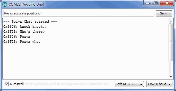
Open up the chat room example in the Arduino IDE under File > Examples > Pozyx > chat_room. This example requires two or more pozyx shields and an equal number of Arduino's. In this example, it will be possible to chat wirelessly with all pozyx devices in range. Below is a figure of two devices talking. To run this demo, make sure that the serial monitor runs at 115200 baud with "both NL & CR" enabled.
Interpreting the LEDs: When this program is running, the Rx LED should be blinking, indicating that the Pozyx shield is listening for incoming data. Also LED1 should be blinking at a low frequency to indicate that the pozyx system is working properly. When this LED stops blinking, something went wrong. Finally, the TX led will blink shortly whenever you transmit a message.
The Arduino code explained
The Arduino sketch code begins as follows:
#include <Pozyx.h>
#include <Pozyx_definitions.h>
#include <Wire.h>
uint16_t source_id;                 // the network id of this device
uint16_t destination_id = 0;        // the destination network id. 0 means the message is broadcasted to every device in range
String inputString = "";            // a string to hold incoming data
boolean stringComplete = false;     // whether the string is complete
It can be seen that the sketch requires two pozyx files: "Pozyx.h" and "Pozyx_definitions.h" which contains the Pozyx Arduino library,and the "Wire.h" file for the I2C. After that, there are a number of global variables defined.
Next, we look at the setup() function. This function runs only once when the Arduino starts up.
void setup(){
  Serial.begin(115200);
  // initialize Pozyx
  if(! Pozyx.begin(false, MODE_INTERRUPT, POZYX_INT_MASK_RX_DATA, 0)){
    Serial.println("ERROR: Unable to connect to POZYX shield");
    Serial.println("Reset required");
    abort();
  }
  // read the network id of this device
  Pozyx.regRead(POZYX_NETWORK_ID, (uint8_t*)&source_id, 2);
  // reserve 100 bytes for the inputString:
  inputString.reserve(100);
  Serial.println("--- Pozyx Chat started ---");
}
From the code it can be seen that the Serial port is used at 115200 baud (~= bits per second). The other parameters for the serial port are default, i.e., 8bits, no parity, 1 stop bit. Next, the Pozyx device is initialized. The Pozyx.begin(boolean print_result, int mode, int interrupts, int interrupt_pin) function takes up to 4 parameters. This function checks that the Pozyx device is present and working correctly. The first parameter indicates if we want debug information printed out, the second describes the mode: MODE_POLLING or MODE_INTERRUPT. Using the polling mode, the Arduino will constantly poll (ask) the Pozyx shield if anything happened. Alternatively, the interrupt mode configures the pozyx device to give an interrupt signal every time an event has occurred (this is the preferred way). The events that should trigger in interrupt are configured by the interrupts parameter (more information about interrupts here). Lastly, with interrupt_pin it is possible to select between the two possible interrupt pins (digital pin 2 or 3 on the Arduino).
Here, the pozyx device is configured such that it doesn't output debug data, and that it uses interrupt using interrupt pin 0. With POZYX_INT_MASK_RX_DATA interrupts will be triggered each time wireless data is received.
Next, the setup function reads out the 16 bit network id of the pozyx shield (this is the hexadecimal number printed on the label), and stores it in the global variable source_id. Notice that the regRead function works with bytes, so we indicate that we want to read 2 bytes starting from the register address POZYX_NETWORK_ID and store those to bytes in the byte pointer. Finally, 100 bytes are reserved for the input string.
The code for the main loop is listed below:
void loop(){
  // check if we received a newline character and if so, broadcast the inputString.
  if(stringComplete){
    Serial.print("Ox");
    Serial.print(source_id, HEX);
    Serial.print(": ");
    Serial.println(inputString);
    int length = inputString.length();
    uint8_t buffer[length];
    inputString.getBytes(buffer, length);
    // write the message to the transmit (TX) buffer
    int status = Pozyx.writeTXBufferData(buffer, length);
    // broadcast the contents of the TX buffer
    status = Pozyx.sendTXBufferData(destination_id);
    inputString = "";
    stringComplete = false;
  }
  // we wait up to 50ms to see if we have received an incoming message (if so we receive an RX_DATA interrupt)
  if(Pozyx.waitForFlag(POZYX_INT_STATUS_RX_DATA,50))
  {
    // we have received a message!
    uint8_t length = 0;
    uint16_t messenger = 0x00;
    delay(1);
    // Let's read out some information about the message (i.e., how many bytes did we receive and who sent the message)
    Pozyx.getLastDataLength(&length);
    Pozyx.getLastNetworkId(&messenger);
    char data[length];
    // read the contents of the receive (RX) buffer, this is the message that was sent to this device
    Pozyx.readRXBufferData((uint8_t *) data, length);
    Serial.print("Ox");
    Serial.print(messenger, HEX);
    Serial.print(": ");
    Serial.println(data);
  }
}
In the main loop, the system waits for any of the following two events:
The user has written some text and pressed enter which is checked by the if-statement if(stringComplete). When this happened, the program will show the text in the user terminal and broadcast the text. The text is broadcasted using the following two statements: Pozyx.writeTXBufferData(buffer, length);, which puts the data in a transmit buffer, ready for transmission, and Pozyx.sendTXBufferData(destination_id); to acutally transmit the data to the device with the give destination_id. In this example, destination_id is set to 0, meaning that the message is broadcasted (everyone will receive it).
The Pozyx device has received a wireless message. This is checked by Pozyx.waitForFlag(POZYX_INT_STATUS_RX_DATA,50). The waitForFlag waits for the RX_DATA interrupt for a maximum of 50ms. If the interrupt happened, the function returns success. At this point, the length of the message, and the network id of the device sending the message is obtained using Pozyx.getLastDataLength(&length); and Pozyx.getLastNetworkId(&messenger);. On the Pozyx device, the content of the received message is stored in the RX buffer. This content can be read using Pozyx.readRXBufferData((uint8_t *) data, length);.
This concludes the last example that is included in the Pozyx Arduino Library. Make sure to check out our Tutorials section where we will regularly post some new tutorials. If you have any requests for tutorials or if you have a tutorial of your own, please send us a message at info@pozyx.io.