Configuration of the UWB parameters (Arduino)
The different UWB parameters
The selection of the ultra-wideband (UWB) parameters can be an important design choice. In this tutorial we explain how you can change the UWB settings and how this impacts the system's performance. Typically, the UWB parameters will impact the update rate, the range and the connectivity between devices. It is very important to realize that devices with different UWB settings may not be able to communicate with each other. Always make sure that all devices (tags and anchors) are using the same UWB settings in your application.
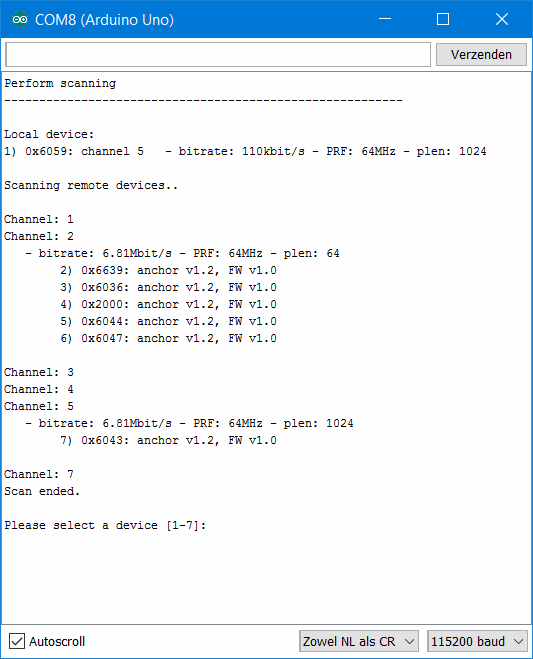
For this part, no coding is necessary as we will use one of the Arduino sketches included in the Pozyx library that will guide you through the configuration. Start by opening the sketch pozyx_UWB_configurator that can be found under File > Examples > Pozyx > useful. Upload the sketch to an Arduino equipped with a Pozyx shield and open the serial monitor. Once the sketch starts, it will search and show all Pozyx devices in range with their respective UWB configuration settings. This is an example output of the sketch as viewed in the serial monitor:

The UWB configurator has found 6 pozyx anchors, of which 5 are configured on channel 2 and, one is configured on channel 5.
After scanning, it is possible to select one of the devices and change its UWB settings. The new settings will be saved to the flash memory of the selected device and the device will keep using these settings even after restart. The following settings can be set:
channel This sets the UWB channel. The pozyx device can use 6 independent UWB channels. Devices on different UWB channels cannot communicate and do not interfere with each other. In general, lower frequencies (i.e., lower channel numbers) also result in an increased communication range. More details can be found in the register description of POZYX_UWB_CHANNEL
bitrate This sets the UWB bitrate. Three possible settings are possible: 110kbit/sec, 850kbit/sec and 6.81Mbit/sec. A higher bitrate will result is shorter messages and thus faster communication. However, this comes at the expense of a reduced operating range. The effect of the bitrate on the duration of ranging or positioning is shown in the figures below. More details can be found in the register description of POZYX_UWB_RATES
pulse repetition frequency (PRF) This sets the UWB pulse repetition frequency. Two possible settings are possible: 16MHz or 64MHz. This settings has little effect on the communication rate. However, on the same UWB channel, these two settings can live next to each other without interfering. More details can be found in the register description of POZYX_UWB_RATES
preamble length This sets the UWB preamble length. This setting has 8 different options: 4096, 2048, 1536, 1024, 512 , 256 , 128 , or 64 symbols. A shorter preamble length results in shorter messages and thus faster communication. However, this again comes at the expense of a reduced operating range. The effect of the preamble length on the duration of ranging or positioning is shown in the figures below. More details can be found in the register description of POZYX_UWB_PLEN
From this, we can conclude that by changing the channel and PRF settings, up to 12 systems can run independently from each other. For the highest possible update rate (with the shortest range), the bitrate should be set to 6.81Mbit/sec and the preamble length to 64 symbols. Conversely, for the lowest possible update rate with the best range the bitrate should be set to 110kbit/sec with a preamble length of 4096 symbols, preferably on the first channel.
Make sure to enter 'save' after reconfiguring each device with the UWB_configurator sketch to save the settings in flash.
Doing it in code
An overview of all the Arduino functions that can be used to manipulate the UWB settings in code can be found in the Arduino library documentation. Note that in order to save the settings for the next reset, it is required to use the function saveConfiguration().
