Tutorial 1: Ready to range (Arduino)
Ready to range
This is the first general Pozyx tutorial for the Creator system. If you haven’t read the getting started, please do so and install the necessary tools and libraries.
This example requires two Pozyx devices and one supported Arduino device. Remember that we recommend the Arduino Uno Rev. 3. If all tools are installed, open up the ready to range example in the Arduino IDE under File > Examples > Pozyx > ready_to_range.
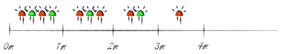
In this example, the distance between the two devices is measured and the onboard LEDs will show in which range the devices are to each other. The destination Pozyx's LEDs will be doing the same, commanded by our local Pozyx. The LEDs' changes with respect to the distance is sketched in the figure below:
Plug and play
To see the tutorial in action before we delve into the code, the parameters will need to be changed to match your destination device's ID.
You also have to set the Arduino IDE’s serial monitor’s baudrate to 115200. At the top of the Arduino sketch, we find the sketch’s parameters:
uint16_t destination_id = 0x6670; // the network ID of the ranging destination
signed int range_step_mm = 1000;  // distance between each LED lighting up.
uint8_t ranging_protocol = POZYX_RANGE_PROTOCOL_PRECISION; // the ranging protocol to use.
uint16_t remote_id = 0x605D;      // the network ID of the remote device
bool remote = false;              // whether to use the given remote device for ranging
You’ll have to change the destination_id parameter to the ID of your destination Pozyx. Optionally, you can change the range_step_mm as well, which will make the distance range indicated by the LEDs either higher or lower depending on your change. remote_id and remote will allow measuring the distance between two remote Pozyx devices, and will be explained at the end of this tutorial, so don't change those for now.
The ranging_protocol is a new feature that allows changing between two ranging protocols: POZYX_RANGE_PROTOCOL_FAST and POZYX_RANGE_PROTOCOL_PRECISION. Precision is slower, but more precise and can be used on longer ranges. The fast protocol needs to warm up for about 100ms before. If this has piqued your interest, definitely check the system performance section in the datasheet!
If you’ve correctly changed your device ID, run the example! You should see that the LEDs of your two Pozyx devices now burn identically, and change when you move them closer or further apart. The output you’re receiving will look like this:
16691ms, 7564mm, -93dBm
16753ms, 7718mm, -91dBm
16830ms, 7779mm, -92dBm
etc...
The first value is the device’s timestamp of the range measurement. The second value then is the measured distance between both devices. The third value, expressed in dBm, signifies the signal strength, varying between -79 and -103 dB typically. You might be reading either:
0ms, 0mm, 0dB
or
ERROR: ranging
If this is the case, you probably miswrote the ID (did you write it with the 0x prefix?) or your device is not in range currently. As the LEDs will only indicate differences of a meter by default, keeping the distance between a couple of meters for this first try is recommended. If the error persists despite having put in everything correctly, check out the troubleshooting guide.
If you’re getting gibberish, you probably forgot to set your serial monitor’s baudrate to 115200.
The code explained
Now that you’ve had a taste of what exactly this example provides, let’s look at the code that provides this functionality. We’ll begin with the imports and the setup functions, and then go into the continuous loop.
Imports
#include <Pozyx.h>
#include <Pozyx_definitions.h>
#include <Wire.h>
We can see that the sketch requires both “Pozyx.h” and “Pozyx_definitions.h”, and the "Wire.h" file for the I2C.. “Pozyx.h” provides the library’s functionality, “while Pozyx_definitions.h” provides constants such as POZYX_SUCCESS and POZYX_FAILURE, register addresses… these are useful to keep your code working with both current, previous, and future versions of the library.
Setup
This function will run only once, when the Arduino is powered on or reset. It sets up the serial communication at 115200 baud, so be sure to set your Serial Monitor to this same baudrate if you hadn’t already. The Pozyx is then initialized by calling Pozyx.begin() , which checks whether the Pozyx is connected and working properly.
void setup(){
  Serial.begin(115200);
  if(Pozyx.begin() == POZYX_FAILURE){
    Serial.println("ERROR: Unable to connect to POZYX shield");
    Serial.println("Reset required");
    delay(100);
    abort();
  }
  // setting the remote_id back to NULL will use the local Pozyx
  if (!remote){
    remote_id = NULL;
  }
  Serial.println("------------POZYX RANGING V1.0------------");
  Serial.println("NOTES:");
  Serial.println("- Change the parameters:");
  Serial.println("\tdestination_id (target device)");
  Serial.println("\trange_step (mm)");
  Serial.println();
  Serial.println("- Approach target device to see range and");
  Serial.println("led control");
  Serial.println("------------POZYX RANGING V1.0------------");
  Serial.println();
  Serial.println("START Ranging:");
  // make sure the pozyx system has no control over the LEDs, we're the boss
  uint8_t led_config = 0x0;
  Pozyx.setLedConfig(led_config);
  // do the same with the remote device
  Pozyx.setLedConfig(led_config, destination_id);
}
Depending on the value of the remote parameters, we set the remote_id to use either the local or a remote Pozyx. After initializing the Pozyx, we configure both the local and destination Pozyx’s LEDs to be in our control instead of displaying system status, which is their default behavior. This is done by setting the POZYX_CONFIG_LEDS register’s value to 0b00000000 on both devices. While the library’s functionality hides away a lot of low-level functionality, it’s important to know how to access registers directly low-level and to find your way in the register overview for your own personal goals. These core low-level functions are:
static int regRead(uint8_t reg_address, uint8_t *pData, int size);
static int regWrite(uint8_t reg_address, const uint8_t *pData, int size);
static int regFunction(uint8_t reg_address, uint8_t *params, int param_size, uint8_t *pData, int size);
and the remote equivalents
static int remoteRegWrite(uint16_t destination, uint8_t reg_address, uint8_t *pData, int size);
static int remoteRegRead(uint16_t destination, uint8_t reg_address, uint8_t *pData, int size);
static int remoteRegFunction(uint16_t destination, uint8_t reg_address, uint8_t *params, int param_size, uint8_t *pData, int size);
Loop
Let’s move on to the loop function, which will run continuously and executes the ranging functionality.
void loop(){
  device_range_t range;
  int status = 0;
  // let's perform ranging with the destination
  if(!remote)
    status = Pozyx.doRanging(destination_id, &range);
  else
    status = Pozyx.doRemoteRanging(remote_id, destination_id, &range);
  if (status == POZYX_SUCCESS){
    Serial.print(range.timestamp);
    Serial.print("ms, ");
    Serial.print(range.distance);
    Serial.print("mm, ");
    Serial.print(range.RSS);
    Serial.println("dB");
    // now control some LEDs; the closer the two devices are, the more LEDs will be lit
    if (ledControl(range.distance) == POZYX_FAILURE){
      Serial.println("ERROR: setting (remote) leds");
    }
  }
  else{
    Serial.println("ERROR: ranging");
  }
}
In the loop function, ranging is performed with the Pozyx library’s doRanging function. The range information will be contained in device_range.
When we want to perform ranging on a remote Pozyx, we use doRemoteRanging instead. The device_range variable is an instance of the device_range_t structure. Looking at its definition (in Pozyx.h) we can see that the device range consists of three variables providing information about the measurement. By using the __attribute__((packed)) attribute, the struct’s bytes are packed together.
typedef struct __attribute__((packed))_device_range {
  uint32_t timestamp;
  uint32_t distance;
  int8_t RSS;
}device_range_t;
In a wireless system, we don’t want to waste transmission time on unused padding bytes, after all. The library provides similar structures for all relevant data structures related to Pozyx, which you'll encounter if you follow the other tutorials and get into further reading. The measurement consists of the timestamp in milliseconds, the measured distance in mm and the RSS-value (the received signal strength) expressed in dBm. Depending on the UWB settings, -103 dBm is more or less the lowest RSS at which reception is possible, and -80 is a normal value for devices close to each other. Upon a successful measurement, these three variables are printed and the LEDs are updated with the ledControl function.
ledControl
int ledControl(uint32_t range){
  int status = POZYX_SUCCESS;
  // set the LEDs of the pozyx device
  status &= Pozyx.setLed(4, (range < range_step_mm), remote_id);
  status &= Pozyx.setLed(3, (range < 2*range_step_mm), remote_id);
  status &= Pozyx.setLed(2, (range < 3*range_step_mm), remote_id);
  status &= Pozyx.setLed(1, (range < 4*range_step_mm), remote_id);
  // set the LEDs of the destination pozyx device
  status &= Pozyx.setLed(4, (range < range_step_mm), destination_id);
  status &= Pozyx.setLed(3, (range < 2*range_step_mm), destination_id);
  status &= Pozyx.setLed(2, (range < 3*range_step_mm), destination_id);
  status &= Pozyx.setLed(1, (range < 4*range_step_mm), destination_id);
  // status will be zero if setting the LEDs failed somewhere along the way
  return status;
}
The ledControl function turns the LEDs on or off if they fall within a certain range, using a simple boolean expression, for example,
range < 3*range_step_mm, which returns true if the distance is within three times the range_step_mm parameter.
Nothing is stopping you from designing your own ledControl function, where you can use other indexes or, as a challenge, even use the four LEDs as 4 bits indicating up to sixteen range_step_mm differences instead of four.
Remote operation
As you have probably seen when looking at the code and the register functions, Pozyx is capable of communicating with remote Pozyx devices: thanks to UWB communication, we can perform every local functionality on a remote device as well. In this tutorial, this can be done by changing the remote_id and remote parameters. Setting remote = true; will perform all the functionality on a device with ID remote_id, so you will need to set that ID correctly as well and own three devices to perform remote ranging.
A general rule with the Pozyx API is that almost every function has remote_id as a keyword argument, which allows the writing of code that can easily switch between being executed locally or remotely, as seen in this example. When remote_id is uninitialized, the function will be executed locally.
The disadvantages of working remotely need to be kept in mind, however. The possibility of losing connection, something that is much harder with a cable. A delay, as the UWB communication between both devices is not instantaneous. And you need a local controller, which is an extra device in your setup. In turn, you gain a lot of mobility, as the remote device only needs to be powered, not needing a controller.
This concludes the first Pozyx example. In the next example, we’ll cover positioning and the necessary setup to perform positioning successfully.