Mounting the anchors
Which cables to use
We refer to our documentation page dedicated to cables:
Which switches to use
An anchor uses ± 5 W (watt), therefor your switches should:
Have PoE+ (802.3at)
Deliver at least (5 W x max number of anchors connected on 1 port) per port.
E.g. If you want to go up to 5 anchors on a chain you'll need a switch that delivers at least 5 W x 5 = 25 W per port.Deliver at least (5 W x total number of anchors connected to the switch) in total.
E.g. If you want to have 16 anchors connected to the switch you'll need a switch that delivers at least 5 W x 16 = 80 W in total.
For smaller setups we can recommend the Ubiquiti UniFi Switch 8-150W (https://www.ui.com/unifi-switching/unifi-switch-8-150w/) as an affordable and good price-quality switch.
Mounting the anchors
For more details regarding the physical anchor installation with different brackets we refer to our more detailed instruction videos.
Connecting the anchors
The anchors each have two ethernet (RJ45) ports labeled port 1 and port 2.
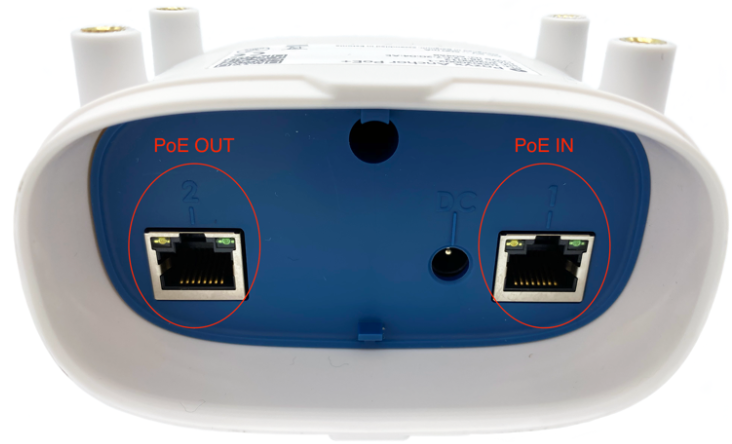
These ports can be used to link up anchors in sequence which reduces the total amount of wiring required, we call this daisy chaining of anchors. With this method power only has to be provided to port 1 of the first anchor in the chain. The next anchor can be powered by connecting a cable from port 2 of the powered anchor to port 1 of the next anchor and so on. The first anchor can be powered in two ways, either using the DC power jack, or by Power over Ethernet. For Power over Ethernet, PoE+ (802.3at) is required.
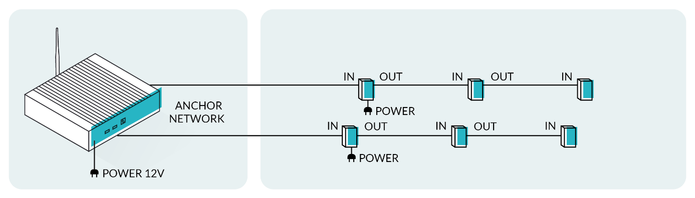
Using DC jacks to power the first anchor in each chain
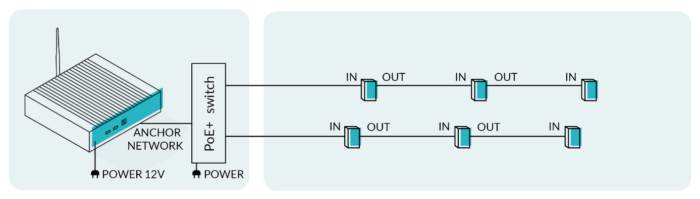
Using a PoE+ switch to power each chain
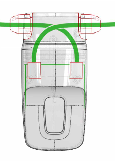
PoE IN and OUT-going cables should be installed in a crossed way when using the IP67 header
The maximum number of anchors in one chain depends on how they are powered, and the quality of the cables. Using cables and switches which comply with our specs you'll be able to have a maximum of 5 anchors on a chain, with a maximum of 80 m between each anchor. The total cable length of the daisy chain is therefore limited to 400 m. More anchors on a single chain will cause issues.
Validating the anchors
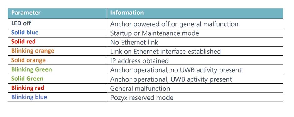
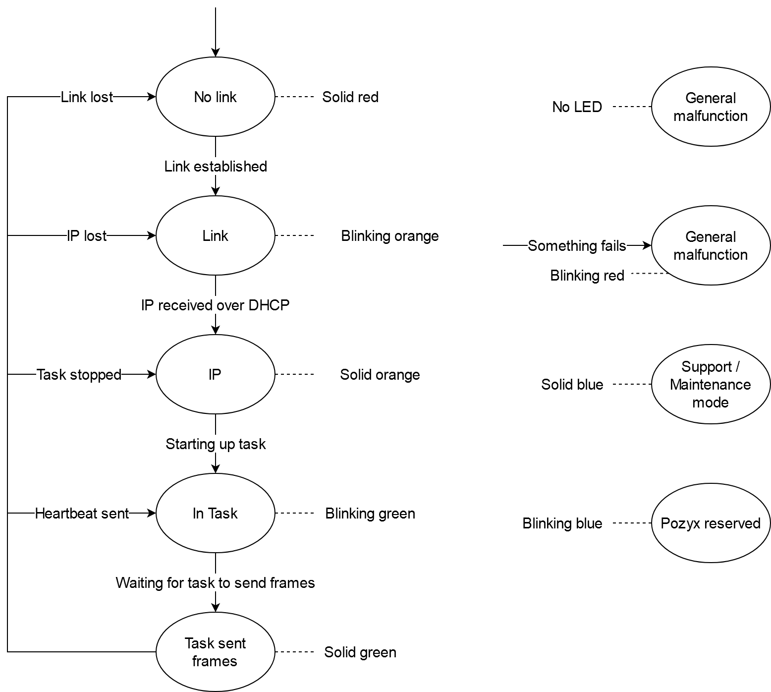
Each anchor has a LED light on it which will give you feedback about the current state of the anchor. This LED light can be very useful during installation to detect problems on the spot, and will allow you to take immediate action on common issues like cabling issues. But the LED will only give you useful feedback when the anchor gets connected to the positioning server, which means it's best to already have the positioning server and switches in place before the installation of the anchors.
When you plug in the Ethernet cable in the anchor, and it gets power, the anchor will start up in bootloader mode in which the LED will be blue. After approximately 7 seconds the anchor will then go to the firmware and follow this flow:
1 https://www.showmecables.com/blog/post/copper-clad-aluminum-vs-pure-copper-cables
2 https://www.cablesandkits.com/faq/what-is-the-difference-between-utp-stp-ftp-sftp
4 https://en.wikipedia.org/wiki/American_wire_gauge
5 https://www.comms-express.com/infozone/article/t568a-and-t568b/
*The minimal cable requirements are valid for anchor with hardware version v2.1 and higher